solar / radio / home-assistant
Replacing the SolarCity monitoring box with a local radio collector
Reading a Power-One inverter locally with a SMLIGHT radio bridge and Python, without the original SolarCity monitoring box.
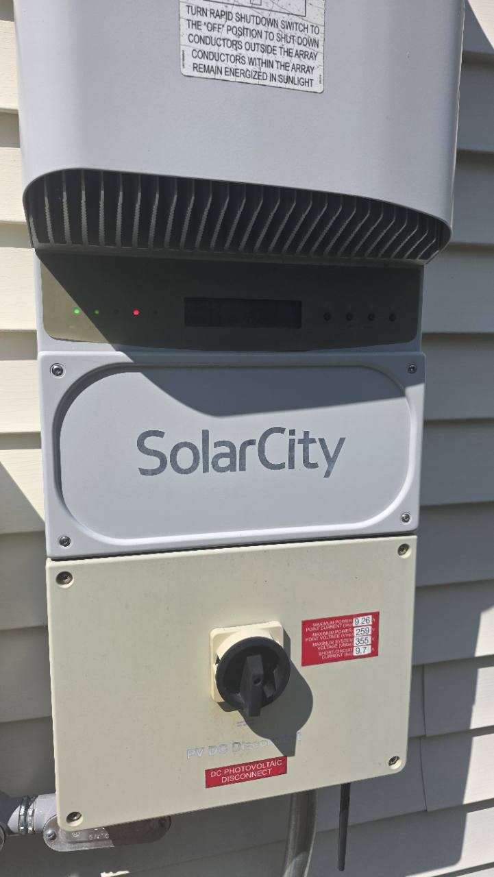
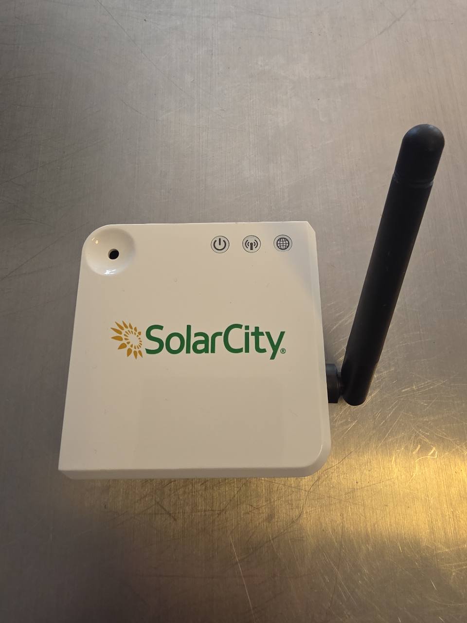
Code & setup instructionsMy solar setup has a Power-One inverter and a SolarCity monitoring box. The inverter sends its readings over a Digi XBee radio. I wanted those readings on my own machine, so I replaced the monitoring box with a SMLIGHT bridge and Python software.
SolarCity Inverter Radio maintains the radio network, answers the inverter’s startup messages, and reads production and diagnostic registers.
I used a Power-One PVI-5000-OUTD-US-Z, its existing Digi XBee radio, and a SMLIGHT SLZB-06U. This is the only hardware combination tested so far. The collector currently requires the original box’s radio identity and network settings. Pairing with a new coordinator identity remains untested.
Radio protocol
The measurements pass through these protocols:
Python collector
    Spinel over TCP
SMLIGHT raw radio
    IEEE 802.15.4 / Digi Zigbee
Inverter XBee radio
    Serial Modbus RTU
Power-One SunSpec registers
The radio payload contains Modbus RTU register reads and replies. These expose power, exported energy, voltage, current, frequency, temperature, and operating state.
Digi documents its serial-data service under application profile 0xc105, cluster
0x0011, and endpoint 0xe8. Those fields provide the route to the serial data
behind the radio. Digi application profile documentation
The supported network uses legacy stack profile 0 and unencrypted packets.
The collector implements the Digi network and application behavior this
inverter expects; radio hardware compatibility alone isn’t sufficient.
Using a network radio from Python
The SLZB-06U exposes its radio through a network serial bridge. That lets the collector run on a machine with no USB connection to the radio.
The tested configuration uses SMLIGHT’s CC2652P OpenThread RCP firmware build
20260304, a 460800 baud serial bridge, and TCP port 6638.
SMLIGHT documents this firmware mode.
Although the firmware is called OpenThread RCP, the project uses it as a raw IEEE 802.15.4 interface. Python supplies the legacy Digi Zigbee frames. There is no Thread network in this arrangement.
The radio handles transmission, reception, frame checksums, and MAC acknowledgments. Python handles coordinator messages, application acknowledgments, measurement requests, and decoding. The repository pins the Python radio dependency to a specific revision so that another person can reproduce the same interface.
A replacement must act as the coordinator
The inverter expects a coordinator that advertises the network and answers the messages needed to stay connected.
The implementation handles beacons, association, device announcements, address verification, direct routing, and recovery after the inverter leaves or rejoins. It accepts only the configured inverter and learns its current short address from identifiable traffic. A remembered address alone is not enough to start polling.
The tested XBee has coordinator verification enabled through JV=1. Digi’s
JV documentation
describes this startup check. The separate timer-based network watchdog was
configured as NW=0, meaning disabled.
Startup exchange
The inverter also sends an application-level startup request. The observed exchange is:
Inverter:   f4 00 01 01 01
Collector:  f5 00 00 00
The collector sends the response on the same Digi profile, serial-data cluster, and endpoints. It uses a fresh APS counter and requests an APS acknowledgment. It also sends the ordinary APS acknowledgment for the incoming request.
A MAC acknowledgment means a radio frame
arrived. An APS acknowledgment confirms delivery at the Zigbee application layer.
The F5 message answers the startup request itself.
The collector reproduces the observed bytes. I haven’t fully decoded the proprietary fields or verified this exchange on other inverter models. An already joined inverter can also proceed to readings without sending this startup message on every reconnect.
Requesting and validating a measurement
A power read in the supported register map asks Modbus unit 1 for five registers
starting at address 40360:
01 03 9d a8 00 05 2b 85That is a complete Modbus RTU request, including its CRC. It sits inside the Digi radio message. TCP is used between Python and the bridge, but the payload is not Modbus TCP and has no Modbus TCP header.
The response contains a power value and scale factor. For a synthetic example,
a raw value of 5000 with scale -1 means 500.0 W. Register values are
big-endian; the Modbus CRC is sent low byte first.
The collector checks identity, addressing, application fields, expected length, and CRC before accepting a reading. It rejects radio errors and unsupported fragmentation. Missing readings remain gaps in the data.
The collector sends one measurement query per minute, with power alternating with energy and diagnostics. Power normally updates every two minutes. Network maintenance continues independently, and packet delivery retries are bounded. The integration reads inverter registers; it does not change inverter operating settings.
Reproducing the setup
The repository includes the collector, decoder, synthetic protocol tests, an optional dashboard, and separate container build targets. The detailed setup guide covers the exact configuration fields and startup sequence.
The main steps are:
- Confirm the inverter and radio match the supported legacy setup.
- Configure the SMLIGHT RCP bridge, then use the included discovery script and report-to-config guide to gather your channel, operating PAN IDs, expected collector EUI, and inverter EUI. Existing captures or accessible radio configuration are also useful sources.
- Review the evidence, put the observed values in
radio.local.json, and validate the file withpython config.py. - Power off the original collector, if present, and give the Python collector exclusive access to the radio bridge after capture has finished.
- Validate fresh readings, then observe startup and overnight recovery.
Run python collector.py for collection and the JSON API on port 8766.
The optional dashboard runs separately with python server.py on port 8765 and
reads the collector API. Home Assistant can use the same API through its REST
sensors; the repository includes a
power and energy example.
Starting or stopping the dashboard does not restart the radio connection, and
API reads do not increase inverter polling frequency.
A capture used to inspect the application exchange needs to include unicast traffic. Stock TI RCP promiscuous reception can miss ACK-requested unicasts, so a quiet capture is not conclusive. An independent, verified sniffer can help during initial characterization; it is not needed for normal operation.
The repository contains fictional identities and synthetic telemetry. Installation configuration, captures, databases, and logs stay out of version control. The collector API and dashboard bind to localhost by default because the data includes information about the local equipment.
Testing and limitations
With the original box powered off, I tested recovery from a radio reset and a leave/rejoin cycle. The original implementation also resumed readings after an overnight quiet period. These tests cover one installation. The standalone repository has offline tests and still needs independent hardware reproductions and longer-term testing.
The included discovery tool can recover candidate settings from inverter traffic and explains the evidence for each value. On an operating replacement network, it recovered all five required radio settings from inverter-originated frames. An inverter that has already left its network may expose less information. Recovering from that state, or teaching it a new coordinator identity, remains unverified.
Related projects
solarcity_sniff records and decodes SolarCity traffic. Other communities have built replacement coordinators for Enecsys and APsystems. Their protocols differ from this inverter’s. More references are in the repository’s sources and credits.